Even though my Freedom 35 has a radar arch on the transom I’m considering mounting the radome on the mast about 10 feet off the deck. I know drilling holes are a big no-no so I’m designing a clamp on type mount which would require no holes. I’m buying the NorthStar broadband so radiation is not an issue and the cabling is a much smaller diameter than your typical radar (cat5 and 4 small wires) and will try an external conduit. If anyone has any suggestions or reccomendations I’d appreciate it.
Thanks, Gordon
Gordon,
Fyne Spirit has the radome screwed to the mast with an internal conduit leading the cable below. I too have picked up the message about being very cautious as regards drilling any holes in the mast and no doubt one of the very learned members on this site will correct me if I am wrong in expressing the following opinion. And that is that the higher up the mast you are working, the less localised stress there will be that could be aggravated by a hole. The working compression and tension loads must diminish with height. To take it to an extreme, ten holes 1 metre from the top of the mast would be unlikely to cause it to fall down, but the same holes near the bottom could be disastrous. My radome is about 6 metres off the deck.
Gordon,
Drilling in CF is i.m.h.o. not such a problem as sometimes thought.
Here’s how my radar is mounted on my mizzen with a standard Edson mast mount:
http://www.flickr.com/photos/alabama_queen/282285817/
It’s been there with sustained winds of 70 knots. My radar is also about 6 meters / 20’ up the mast, like Mike’s.
The only caveat when attaching hardware on carbon fibre (CF) is never ever to use self tapping screws; they pry open the brittle CF laminate. Drill and tap thread and use locktite liberally. Or better, use large stainless rivets, but then you have a hard time removing the riveted piece of hardware lateron. If you use rivets, the securing ‘blob’ should be totally inside the mast, so measure the thickness of the laminate through the holes you use and take long enough rivets.
Good luck and don’t be scared to make a few holes.
Gordon,
I don’t have an answer regarding mounting the radome, but I will make a comment on NorthStar. I’ve owned 3 NorthStar units (951xd, 961x and now a 6100i). I must say that I am quite disappointed with the 6100i. The 961x, which I bought about 9 years ago had much more functionality and a better user interface than then 6100i has. I purchased the 6100i several years ago to act as a backup for a RayMarine C-80. Since then they’ve only come out with 2 software updates, none of which has added any real functionality. I was quite disappointed with this, as this was quite different from my experience with the 961.
Due to the fact that I was a very early adopter of the 961, I got to know the software and repair staff very well. One of the things that I learned was that they don’t have common software code bases for their units, and as a result they don’t share desirable features.
For example, when I bought the 6100i, AIS was just appearing in the consumer market. The 6100i has 2 NMEA interfaces, one of which runs at 38,400 bps, which is the data rate for AIS. I just assumed that they would implement AIS as the 6100i was their new flagship product. Did they ever do it? No!
I’ve found RayMarine much better for upgrading their older units with new functionality. Just be sure that the functionality of the Northstar has everything that you might want or need in the future, as what you see is probably all that you’re going to get.
– Geoff
My radome is on a standard edson mount riveted to my mizzen mast about 15 feet above the deck. Its taken a pounding at sea and their are no signs of stress cracks or movement there or at any other holes in the mast or the various attachment points (mast track rivets, gooseneck etc.).
Alan F-33 Hull # 51
Before I get into a side conversation regarding my radar mounting issues, I’ll ask a question regarding the proposed mounting location: To me it appears that mounting a radar in front of the typical Freedom carbon fiber mast will cause you to loose radar view of a relatively large angle behind the boat due to the mast blocking the radar beam. How wide is this angle and is this acceptable to you? I know that I can definitely see the radar shadow of the 3" pole behind my radar as well as the mast shadow, which is ~20’ forward.
Now onto my own radar mounting conundrums…
This topic is actually something that I’ve been struggling with for several years. I think that it was back in 2005 that I purchased a Questus self leveling (gimbaled) radar mount and moved the radar from the “normal” mounting location which is on a radar pole on the stern of the boat. Here’s a picture of a typical 40/40 setup:

I machined a mount for the Questus which attached to the normal radar mounting plate and allowed it to rotate. However, this setup caused the radar to be dropped about 12-15". Here’s a photo of the current setup:

The problem is that on certain points of sail when the boom rises up, it blocks the radar’s horizon. I may have had this problem all of along, but this setup certainly exacerbates the problem. So, the question is how to solve this. The problem is complicated by all of the antennas (Wifi, Sirius, 3 active + 1 spare GPS) which I also have mounted on the arch above the radar:

At this point my thought is to chop off the top plate and install an extension tube which would be about 18" higher. I would bring an arm forward to which the Questus mount would attach. I’d also remove the current antenna arch and replace it with an arch which would mount on the Questus directly above the radar, keeping the antennas out of the radar beam. Alternately I could just have another arch built that attaches to the main pole, which would keep the weight off of the Questus. Any suggestions on this would be greatly appreciated, as I’ve struggled with this for years, and now that I’m home, I plan to solve it.
– Geoff
Raydome mounting
In the May 2006 issue of Yachting Monthly, a reader’s question about the position of a raydome is answered in brief by one of YM’s panel of experts. Here is the full version of that question and answer.
I’m looking for some advice regarding where to fit a raydome on my yacht (an X-382). I’m planning to fit a Raymarine C series with an 18"
raydome and would like to mount it on the mast of my X-382. Due to the configuration of the rig - triple spreader with a baby stay and high pole uphaul - the lowest point on the front of the mast where it could be mounted without interfering with the rigging is at the level of the second spreaders, about 12 metres up. I’m not keen to put it that high because of the obvious problems associated with putting that much weight at that height and the amount the scanner will move around in even the slightest swell. I’m also not keen on putting a pole on the pushpit.
I have seen some people who mount their radar scanners on the side of their mast. Doing that would allow me to mount the scanner much lower, at around the level of the first spreaders. I would obviously expect some loss of performance on the side that the scanner was looking through the mast. I would be prepared to accept some loss but I don’t want to mount the raydome and then discover that I can’t see a thing. Any advice? Richard Clark, via email
Jason Sidaway, Raymarine’s Senior Product Support Engineer Radome Scanner Installation replies: Mounting of the radome scanner on the mast is very popular and very much typical for yacht installations for 2 main reasons: 1) safety and 2) range, but there are important considerations to take in account when mounting the radome scanner on the mast.
In terms of safety, this offers an ideal location as the transmitter is well above head height avoiding mechanical danger (not so much for a radome scanner as it is enclosed) and electromagnetic contact removing the potential for compromising personal health on-board when the radar system is operated for long periods and minimising exposure to the crew.
With respect to range of the radar system, since radar basically operates at line-of-sight, the suggestion of higher the mounting position, the longer the range performance, but this is not always the case, remembering that a yacht will be moving and the boat will be ‘heeling’ . Therefore the radar antenna will be as well. Increased height will offer improved long-range performance but at the same time, increases the minimum short-range detection circle as well as exaggerate any rolling or pitching motion of the vessel.
Therefore, a compromise as such is necessary in attempt to mount the radar scanner as high as possible but take into consideration, the movement of the vessel… A simple equation can be used to calculate the distance to the radar horizon which is approximately 1.2 times the square root of the height of the scanner. For example, a scanner mounted 20’ above the water-line will provide the radar of 5.4 miles range before the radar beam is ‘blocked’ by the earth’s curvature.
Immediately, you may say this is contrary to the marketed maximum range scale of the radar but there are two factors to take into consideration with regards to radar range: 1) height of the antenna and 2) height of the target, so the same equation can used to determine the targets radar horizon, by using the sum of the distance to the targets radar horizon to the maximum radar horizon to derive the maximum detection range for that target.
So same example, a scanner mounted 20’ above the water-line will provide the radar of 5.4 miles range, radiating a target that is 20’ feet tall, can detect that target at a maximum range of 10.8 miles, also remembering that atmospheric and weather conditions can either increase/decrease the range.
The specified maximum range of a radar antenna is determined solely by the ability for the radar system to transmit a pulse to a maximum range and detect a returning echo, the specified maximum range can be compromised and affected by antenna height, target height, weather, horizon etc etc
As already mentioned the main problem for sailboat installations for radar is ‘heeling’, all Raymarine radar products have a vertical beamwidth of 25 degrees, meaning that 12.5 degrees of the beam is directed downward toward the water and 12.5 degrees directed upward with the centre aimed at the horizon. If the boat is heeling in excess of 12.5 degrees port or starboard, the lower beam will be directed above the horizon and essentially rendering the radar blind in that direction. Additionally, all of the radar energy will be directed into the water, resulting in increased sea clutter… from this aspect, you will heed the benefit a ‘gimbal’ style mast mounting, which will abolish this problem, maintaining the radar antenna parallel to the waterline.
Another factor to take into consideration is ‘blind spots’ which can be evolved as a result of detection of masts and booms, if the antenna is mast-mounted, the radar will block the sight of the radar in the direction of the mast, on a typical mast mounted installation, the radar can be subjected to a blind spot of 1 to 15 degrees wide (this is obviously unavoidable) depending on the mast thickness. However, because this is directly astern, it is relatively of lower concern to the user, as generally the higher risk is forward, port and starboard of the vessel. This is potentially where a backstay installation is preferred with ‘some’ distance between the antenna and the mast, there will be a small blind spot in the direction of the mast.
Additionally, this is also a reason why ‘some’ scanner installations are located aside of the mast on the spreaders as a combination of the movement of the vessel and the intelligent software used within the Raymarine radar products, it is very unlikely to detect a blind spot visually on the radar display.
Therefore, personal view is that a radar antenna mounted on the backstay using a gimballed mounting is the best choice for a sailboat, although you will sacrifice range performance by mounting the antenna lower and at the same time increasing short range detection, and you will minimise the probability of blind spots BUT remembering the safety aspect with an antenna mounted overhead.
Typically, a radome scanner when mast mounted will be installed on the forward facing of the mast and in some cases, is protected using a radar guard to prevent the sails and rigging from ‘hitting’ or ‘snagging’ on the radome scanner.
With the cable run, a high number of sailboats are removed from the water and the mast is ‘stepped’.It is recommended that the cable is passed through a waterproof deck gland and a suitable junction is applied to the cable using a suitable waterproof junction box, located inside the boat.
CONCLUSION: the preferred mounting would be on the cross-trees as initially suggested by the customer, offsetting the antenna on the cross-trees should not present a hindrance to the performance of the radar system; in terms of mounting the scanner to the mast, Raymarine do supply a standard mast mounting bracket which would not facilitate the required mounting, suggestion would be to contact Scanstrut (www.scanstrut.com) for recommended mounting solutions but the probability is that a purpose-fabricated bracket will be necessary.
Yachting Monthly, 12 April 2006
Geoff,
I always heard that carbon fiber masts give no radar echo. So would they produce a blind spot?
Michel,
Based upon my observations, I assert that carbon fiber masts are not transparent to radar and I will also assert that on carbon fiber masts are larger than aluminum masts, making the radar shadow area much larger. I will agree that they don’t reflect radar, but that doesn’t mean transparent.
When I look at the photo that Mike posted, it looks like that diameter of the mast is about 2/3 the diameter of the radome. If the dome were in contact with the mast, I think that’s about a 60 degree blank spot (please correct my off the cuff math). To me that’s way too much. I can see the blank spot where through the mast 20’ in front of me and there’s a large spot from the 3" pole.
– Geoff
More than 2 years ago we installed our radome on our mizzen mast using a Hysol aircraft adhesive. It is available in 30cc cartridges and very handy. We mocked up the mount with cardboard and a metal outfit dupicated it in aluminum perfectly. We ran the cable down along the mast outside front - inside some dock bumper material. It all has worked well. If anyone is interested we can find our notes and post more details when we return to Mazatlan and the boat early this fall. Sally and David, Hopalong, Freedom 39 Express (we think #1)
Gluing hardware to CF spars, that’s interesting; we don’t hear much about that here…can you enlighten us a bit, David?
Hi guys, I hope your summer season is going well and you are getting in some sea time!
I note Geoffs comment re blind spot on Fyne Spirit and others wondering about radar performance around CF masts. Last summer sailing down the coast we had a contact/target astern and there did not appear to be much of a blind spot if any, perhaps 5 deg each side of the course line. On the other hand there appears to be a more noticeable blind spot of 4 or 5 degrees each way due to the fore mast. I wonder if the “rear view” is due to the scanner being of greater diameter than the mast, and the tip of it being able to transmit and receive effectively eventhough the mid part would be blocked by the mast.
Regards,
That could be the case. But we’re becoming increasingly aware that CF masts do not reflect radar. One Freedom owner made a trip to Bermuda and was not noticed by the powerful on shore radar of the harbour authorities. He did not have his reflector up, I think. As yet, it’s unclear what happens with radar beams transmitted from a scanner mounted close to the CF mast. It does not sound logical that CF does not reflect radar sent from afar and does reflect radar sent from close by. Anyone having more shreds of evidence in this discussion: please come in!
To start with, found this abstract of an article in the Journal of industrial textiles:
Investigation on the Radar Absorption Properties of Carbon Fiber Containing Nonwovens
Hua Zhu
College of Textiles, Donghua University Shanghai 200051, PR China, xbfyzhuhua@163
Jianchun Zhang
The Quartermaster Research Institute of General Logistics Department of the CPLA Beijing 100088, PR China
Pïng Chen
Department of Electronics Science and Technology Nanjing University, Nanjing 210093, PR China
Xiangcheng Wang
Institute of Chemical Defense Beijing 102205, PR China
Nonwovens containing pitch-based carbon fiber (PCF), polyester fiber, or wool fiber with thermo-bonding fiber 4080 as the bonding agent are fabricated by the through-air thermal bonding process. The volume fraction of carbon fiber in the nonwovens ranges from 0 to 1.5%. Radar wave absorbing properties of the nonwovens are investigated by the far-field RCS measurement in the frequency range from 8 to 18 GHz. Results of the measurement indicate that the radar-absorbing capacity of the nonwovens is closely related to the volume fraction of carbon fiber in the nonwovens and the thickness of the nonwovens, regardless of the types of fiber except PCF in the nonwovens. When the thickness of the nonwovens is 10 mm, radar-absorbing capacity of the nonwovens varies with the content of PCF and reaches the maximum around the PCF volume fraction of 0.036%. When the thickness of the nonwoven with the PCF volume fraction of 0.036% is 6 mm, there appears an absorption peak on the curve of reflectivity at the frequency around 11 GHz, and the absorption in the whole frequency range from 8 to 18 GHz is intensified. Electromagnetic parameters of the component fibers in the nonwovens are tested by the coaxial transmission line method andthe radar absorption characteristics of the nonwovens are explained on the basis of the electromagnetic properties of these fibers.
Key Words: pitch-based carbon fiber • nonwoven • radar absorption • reflectivity • electromagnetic parameters.
Journal of Industrial Textiles, Vol. 37, No. 1, 91-105 (2007)
DOI: 10.1177/1528083707078125
======================================================
Note the mention of an absorbsion peak at 11 Ghz, in the middle of the X-band radar frequency range (8-12 Ghz).
This is what I found on Wikipedia:
Radar Reflection
Electromagnetic waves reflect (scatter) from any large change in the dielectric or diamagnetic constants. This means that a solid object in air or a vacuum, or other significant change in atomic density between the object and what is surrounding it, will usually scatter radar (radio) waves. This is particularly true for electrically conductive materials, such as metal and carbon fiber, making radar particularly well suited to the detection of aircraft and ships. Radar absorbing material, containing resistive and sometimes magnetic substances, is used on military vehicles to reduce radar reflection. This is the radio equivalent of painting something a dark color.
======================================================
Here it says that CF gives a good radar reflection; this is contrary to our believes.
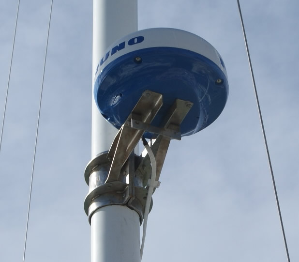
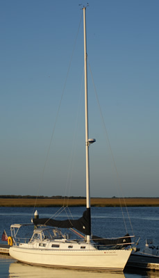
Hi All, Sorry it took so long to get this posted. I ended up having a machine shop fabricate a clamp type mount. No holes neccessary and it has withstood 100+ mph winds here in the FL Keys. Yes it’s overbuilt, but I did not want this thing going anywhere. It weighs 20lbs and made from stainless steel. I used an adhesive conduit from Home Depot to run the wires down the outside of the spar to the display.
greetings from Tampa…
I will be putting radar on my Freedom 40 cat/ketch in a few years…
do you have a picture or specs on building it…
i do have an excellent machine shop here in St.Pete…owner is also a sailor, etc…
thanks…
Capt. Herman
come sail anytime… ![]()
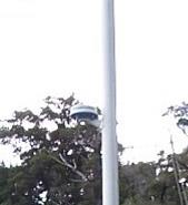
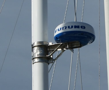
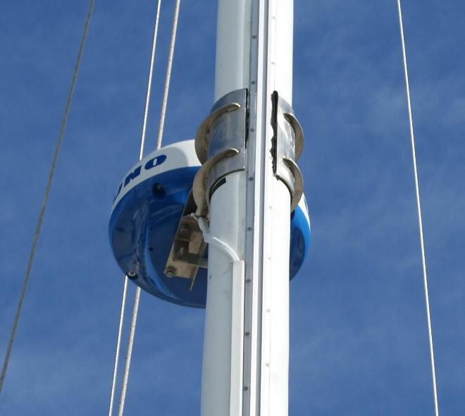
I received an inquiry as to it’s height off the deck etc. So I’m posting it here for everyone. It’s on my Freedom 35 (sloop rig) 19’ off the deck. So it’s about 23’ above the water. When determining the height to mount it I raised the jib in zero wind and looked for the widest point between the leech and mast. This was done to cause the least interference when tacking and so far no problems. I also allowed an extra 1/8" inch of space in the diameter to allow for a rubber gasket to go between the mast and the mount. I didn’t want any “hard” compression between the mount and mast. I felt this would relieve unneccessary stress. I was concerned if it was too tight the mast would snap right above the mount. I’ve included a full size photo below. In the photos you will notice there are three bolts on the front which compress the two halves together. Thus, the amount of compression is adjustable. I was in a big hurry to get it mounted and head south so I haven’t had time to go back up and trim the excess rubber padding to make it look all neat and tidy.
The mount is a one of a kind. I just sketched a design and gave the dimensions to the shop and they fabricated it for me. If I had drawings it wouldn’t be much use unless you were mounting it on a freedom 35 due to varying mast diameters. It does have enough “play” in it where I could move it up or down the rig at least 12-20 inches.
The back of the dome is roughly four inches from the spar and did not experience any blind spots. Even the best autopilot will not steer you in a perfectly straight line so blind spots are not an issue. One last note: you will notice a small horizontal plate along the front and bottom of the mount. This was added so I can mount a foredeck light in the future.
Hi, I’m also thinking possible mountings for a radome. I have a Hoyt 30 cat ketch with (at the moment) wraparound sails, so mounting anything on the mast, either mast, is not an option. Have looked at setups on a transom pole but they look somewhat awkward and in the way of too many other things aft. Did anywone think of a stand-alone pole mounting forward of the main? I though about the interference of the masts but when it comes to compromises, I’d rather have good viz of what lies ahead instead of behind me. Any ideas wellcome! Thanks
I have a f28CK with wrap around sails. I think that mounted on a freestanding pole in front of the mast is a great idea. Since i have not had Raven (my first sailboat) in the water yet; I am not sure how the radar would survive in a pounding sea. Maybe someone with more experience will weigh in.
My boat came with a small radome mounted atop a stern mounted pole.
I chopped the pad off of the top and added an extension, leveling unit and a cross arm for the antennas.
Plus it gave me mini spreaders to hoist flags.

Chuck