Hi everyone,
We have a 1979 Freedom 40, hull #18, with a centerboard, and we have some questions about our bilge layout and ballast.
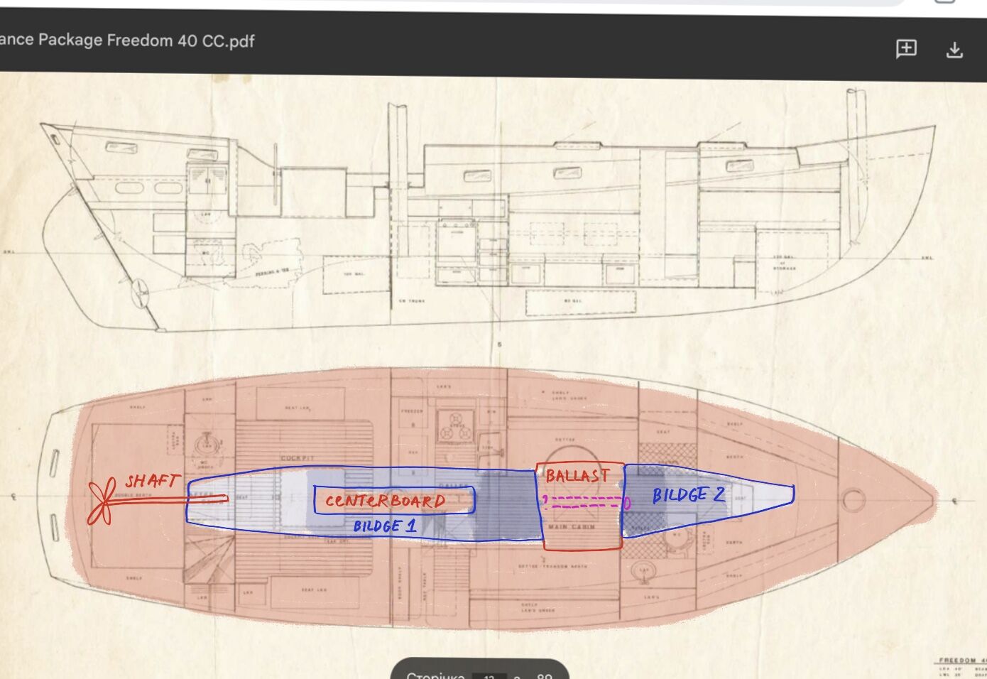
From what we understand now, it seems like we have two separate bilges. I tried to show this on the sketch as Bilge 1 and Bilge 2.
Bilge 1 starts in the aft cabin, where water from the prop shaft drips into it. It runs forward under the engine and through the engine room. When it reaches the centerboard trunk, the trunk divides the bilge into two narrow sections, port and starboard. These run around the trunk, under mizzen mast area and then join back together near the galley in main cabin once the centerboard trunk ends. At the forward end of this bilge, in the main cabin, it gets deeper - I tried to show the different depths with different shades of blue on the sketch.
Bilge 2 starts in the forward cabin. It is narrow at first and runs under the berth, then under the head/shower area, and a small part of it reaches into the main cabin. It also has a deeper area in the main cabin, and then it ends.
A while ago we spent a lot of time testing this by filling both bilges with water. The water never moved from one bilge to the other, so that is how we realized they seem to be separate.
Between these two bilges there is ballast sealed under fiberglass. In a few places the fiberglass structure is damaged/open, and we can see the ballast. It looks like small lead pellets or another metal, I’m not sure. Visually, honestly, it looks like pellets mixed with dirt, but I assume it is supposed to be metal pellets mixed with resin?
Recently we noticed that in Bilge 2, at the very bottom, there is a hole where water drains down. But it does not drain completely: some amount of water collects there and then just stands. We tried pushing a hose into it, flushing it, and putting an endoscope in. There seems to be some kind of pipe or tube continuing from that hole. Draw it with pink on my sketch. It is impossible to get our head in there to see properly, but based on how much hose fits inside, the pipe seems long enough that it should reach toward Bilge 1. But it stops at the end, and in Bilge 1 we cannot find any matching hole, opening, or exit at all.
We also tried pouring warm water into that hole and checking with a thermal camera to see whether anything warmed up in Bilge 1. We thought maybe the two bilges used to be connected and were later glassed over. But the thermal camera did not show anything. We are afraid to pour very hot water in because we do not know what that pipe is made of or what is inside.
So our questions are:
Does anyone have a similar layout or experience with this? How is this supposed to be?
If the two bilges are supposed to be separate, then what is this pipe/hole in Bilge 2 for? Where was it supposed to go, and what was the original design idea?
We also have questions about the ballast. Can someone who understands this construction explain why it was built this way? Do we need to plan any future repair, considering that some of the fiberglass covering over the ballast has opened up?
I am pretty sure water has gotten into that ballast area at times, and maybe some water is still trapped in there.
I have heard of people removing loose lead pellets, melting them into ingots, and placing them back in the keel/ballast area. Does that make any sense in this case, or is it unnecessary?
I can take more photos and videos if needed. I am just not sure how to explain this clearly, so I hope this description makes sense. What do you think?