Glad to read you were able to safely motor back . Though the cause would be interesting to know I am more interested in your thought process and the experience of getting her back to port from sailing perspective. If you feel like sharing. And wish you the best of luck going forward, hoping your freedom is repaired and remains in our fleet.
the passage from hawaii to mexico is not an easy one and as we were only about 450 miles north of hawaii it was a no brainer to turn around we had more than enough fuel to motor sail back to hawaii where we live, mast came down in the middle of the day in good weather while we were down below having lunch , it didnt even make a sound nor did it hit the side of the boat, there was a noticable change in the boat speed and motion so we peeked outside and saw the mast broken over, the sail was half in the water and too heavy to bring back on board , it only took about 30 minits to cut away the sail and spare halyards and lash the stump to the toe rail after that we simply turned around fired up the auto pilot and engine, took 4 days to get back, at no time did we feel that we or the boat was in any danger Adam
I’m glad Adam started this post, I’ve been wanting to post some info to the forum and now I have the motivation. I’m Kevin and I’m doing the repair on Vaimana’s mast. I have it down, prepped and a sleeve made for the repair. I will bond the sleeve in and feather the original mast toward the break zone then build up unidirectional and twill layers of carbon fiber and epoxy to the original diameter. I will also fair out the seam that is about 60 inches above the break area that users noticed. This area has the same sleeve joint as the proposed repair. The sleeve from the original build is about 3-4 feet from the break (I’ll get an actual dimension next visit), It is possible the sleeve created a stress concentration that far away but my gut feeling says not. I made a 3d cad model of the mast and will run a simulation of the mast with and without the sleeve to verify. I surveyed the mast and it doesn’t appear to have circumferential cracking. There is some at the break but it’s hard to tell what came first. I plan on removing some of the paint along the length to see if there is hidden cracking. My repair will also include grinding the gelcoat off about 5 feet below the break to about 5 feet above the original sleeve and applying layers of carbon twill.
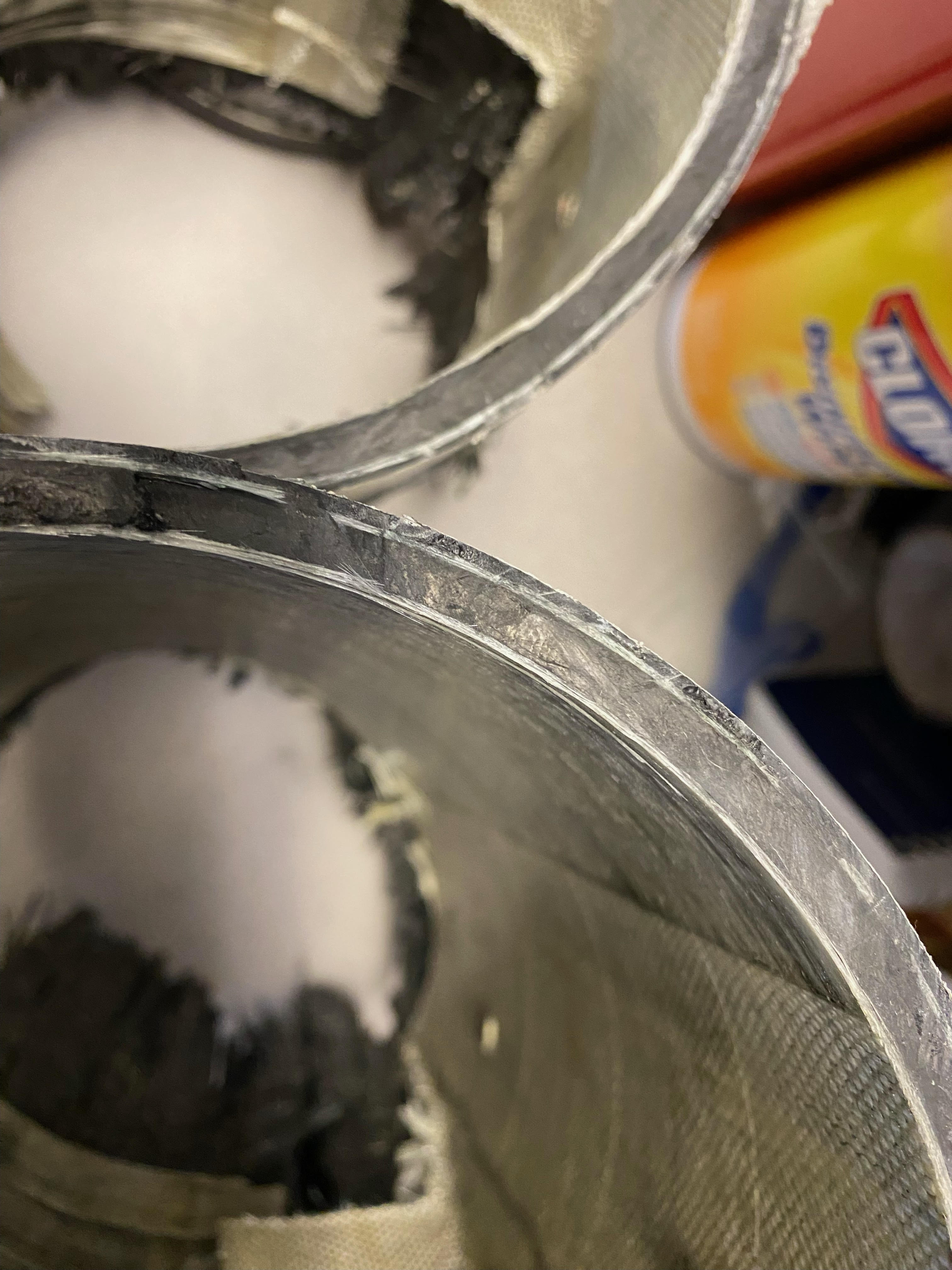
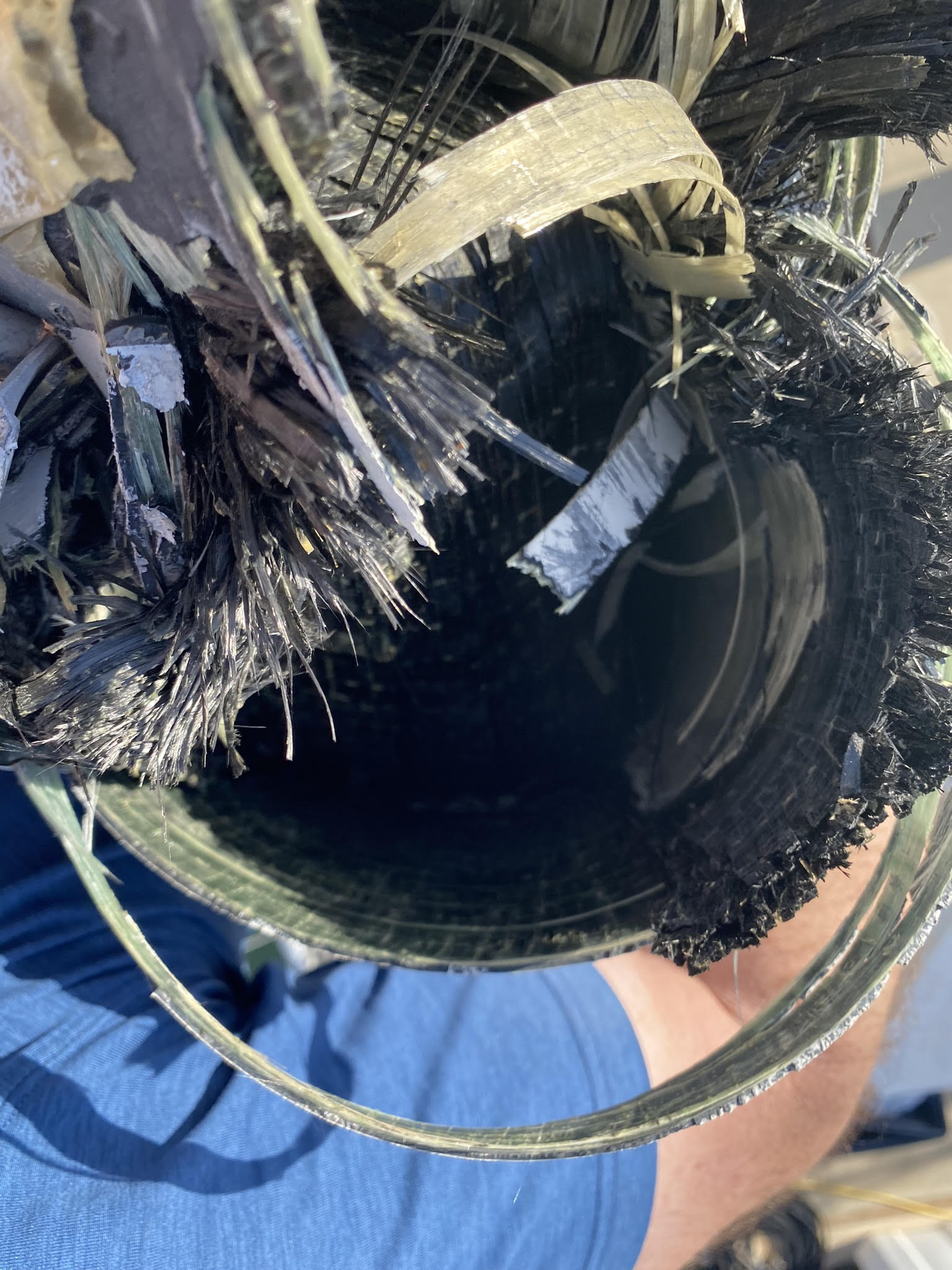
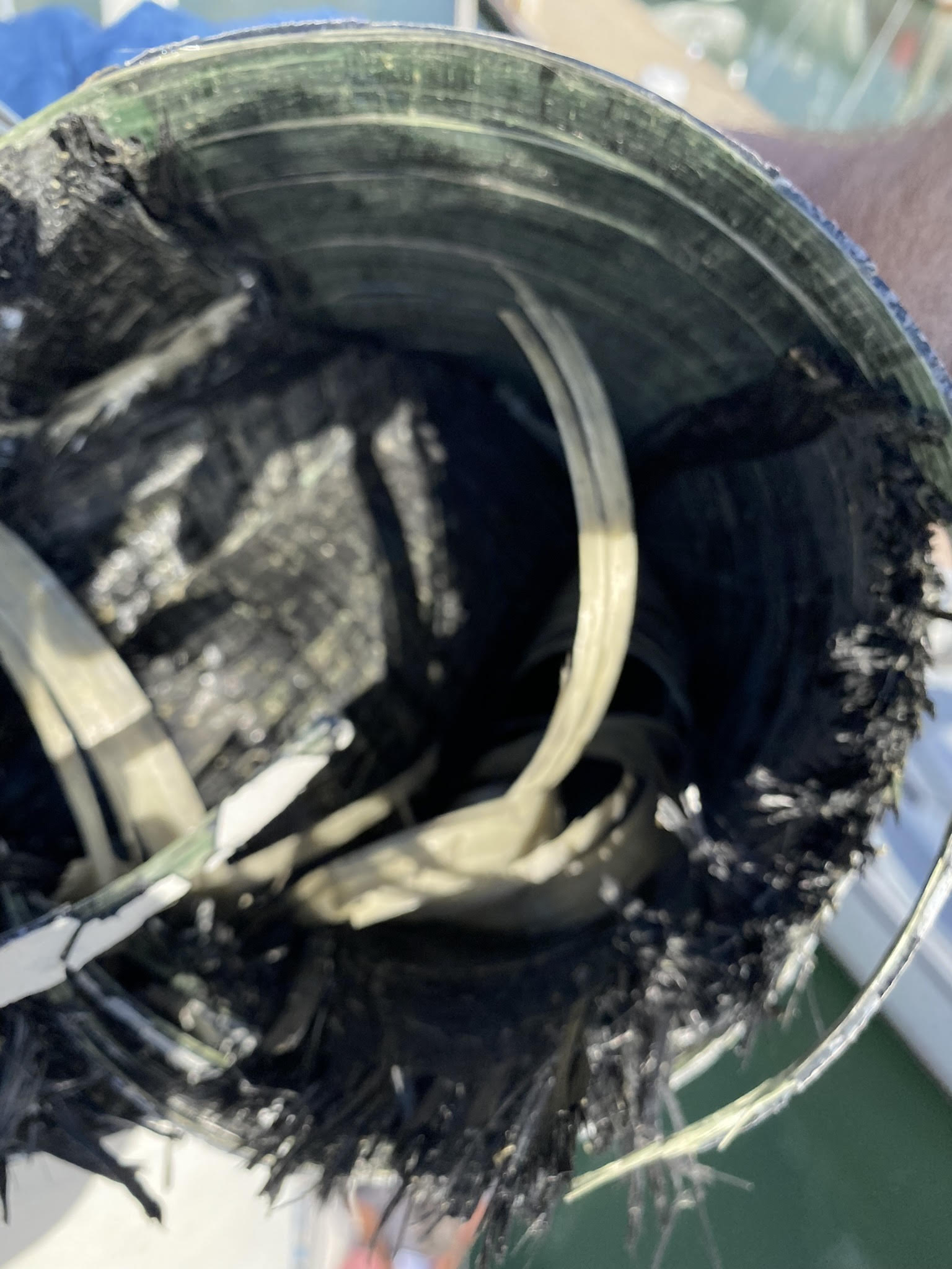
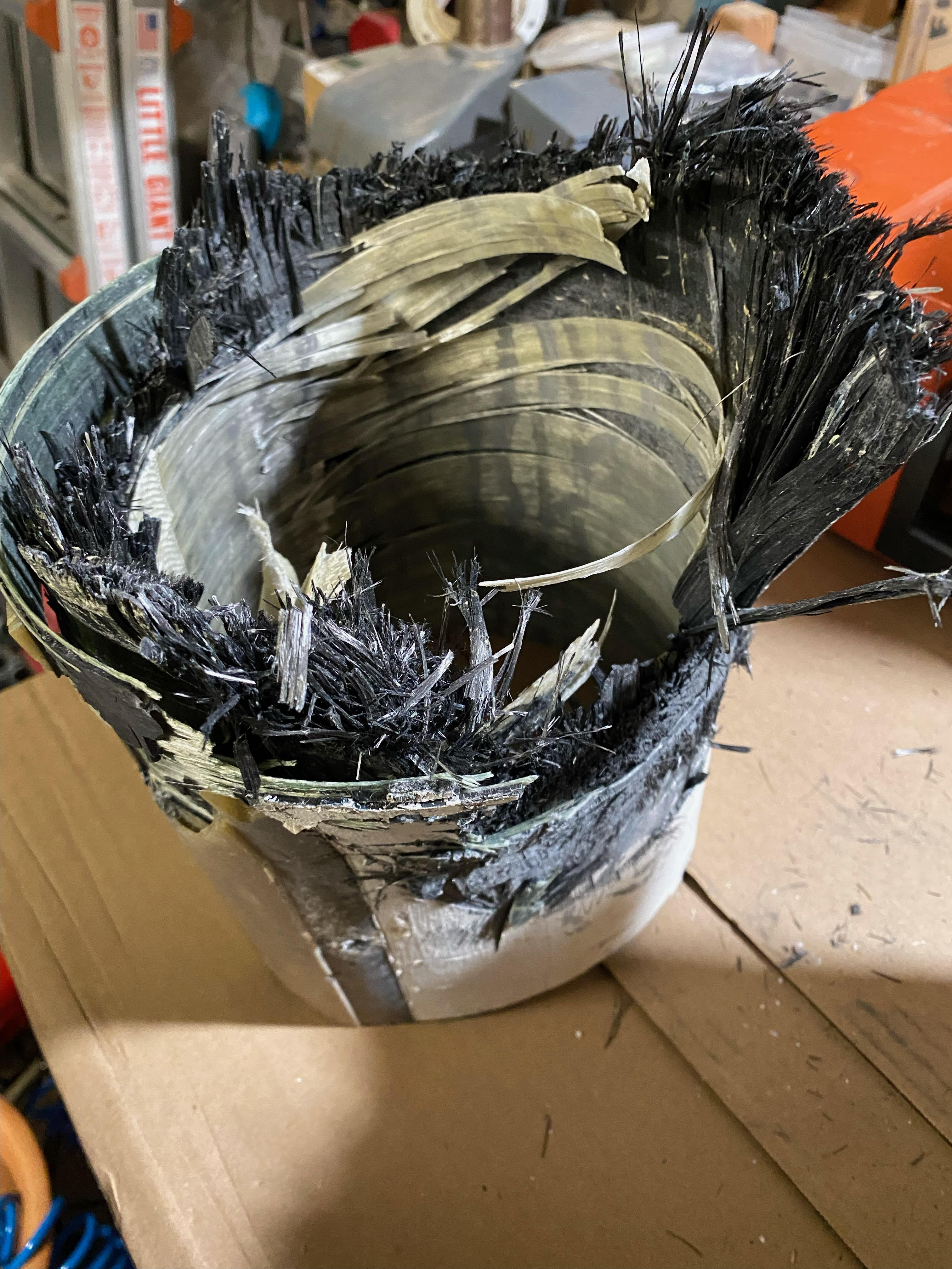
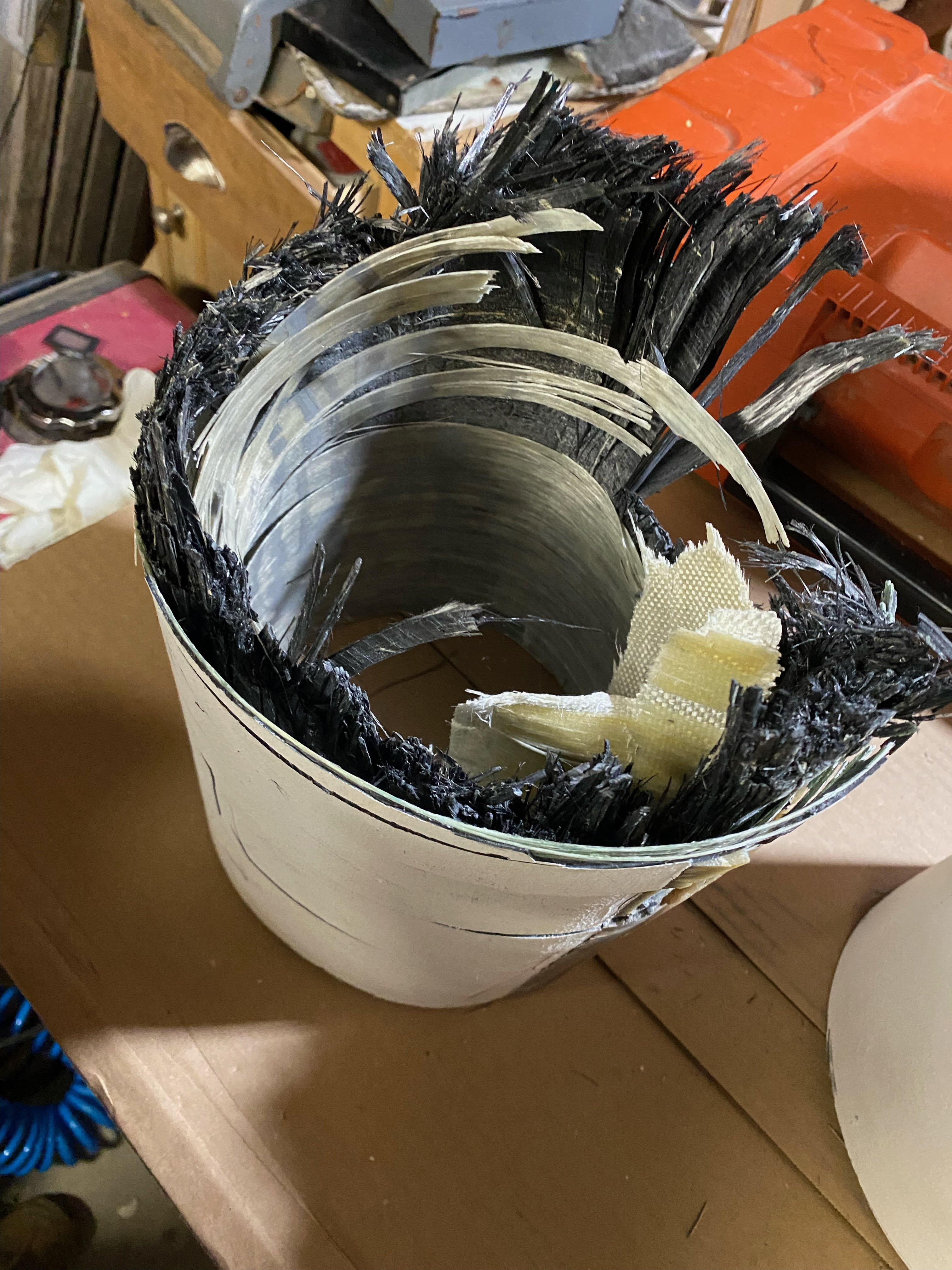
Initial inspection of the fracture is inconclusive, about 2/3 of the fiber stayed intact and just twisted into a bundle (imagine twisting and breaking a piece of celery) There is a fracture zone on the front of the break that looks fairly flush. It shows classic brush like fibers called fiber pull-out. its hard to say if the fibers that bundled up was from fatigue of the epoxy bond causing collapse then the flush break occured or vice versa.
The break does go thru a fastener hole but the fracture of fibers here is at least an inch above this point. I plan on cutting sections of the broken zone out and looking at them in a microscope.
I’ll post progress photos and any new info as I go.
Upper and lower section after removal.
Thank you for taking the time to share detailed descriptions and photos of the repairs your doing, Kevin. This is fascinating.
Aloha Kevin, thanks for chiming in, i have no ax to grind, but feel a responsibility to share this with fellow sailors, at first i was shying away from going public and it was actually mr sphongberg that suggested that i do so , comraderarie of the sea i suppose …
I’m very glad that you decided to of public with this, as all of us carbon-fiber mast owners need to try to understand what happened. There’s absolutely no reason to hide this.
To me, it’s amazing to see the actual failure. It certainly looks a lot different close-up than what I would have imagined from the original photos.
I’m guessing that the damage occurred at some point before the mast came down, and then fatigue caused it to finally fail. I am surprised that you had the mast tapped-out prior to the passage and that it didn’t sound any different.
Please keep the information flowing!
– Geoff
aloha Geoff, there was no damage to the mast prior the failure. Adam
First, solid carbon fiber will not undergo plastic deformation (i.e. yielding). Under load carbon fiber bends, but will not remain in a permanently deformed state once the load is removed. Instead, once the ultimate strength of the material is exceeded, carbon fiber will fail suddenly and catastrophically.
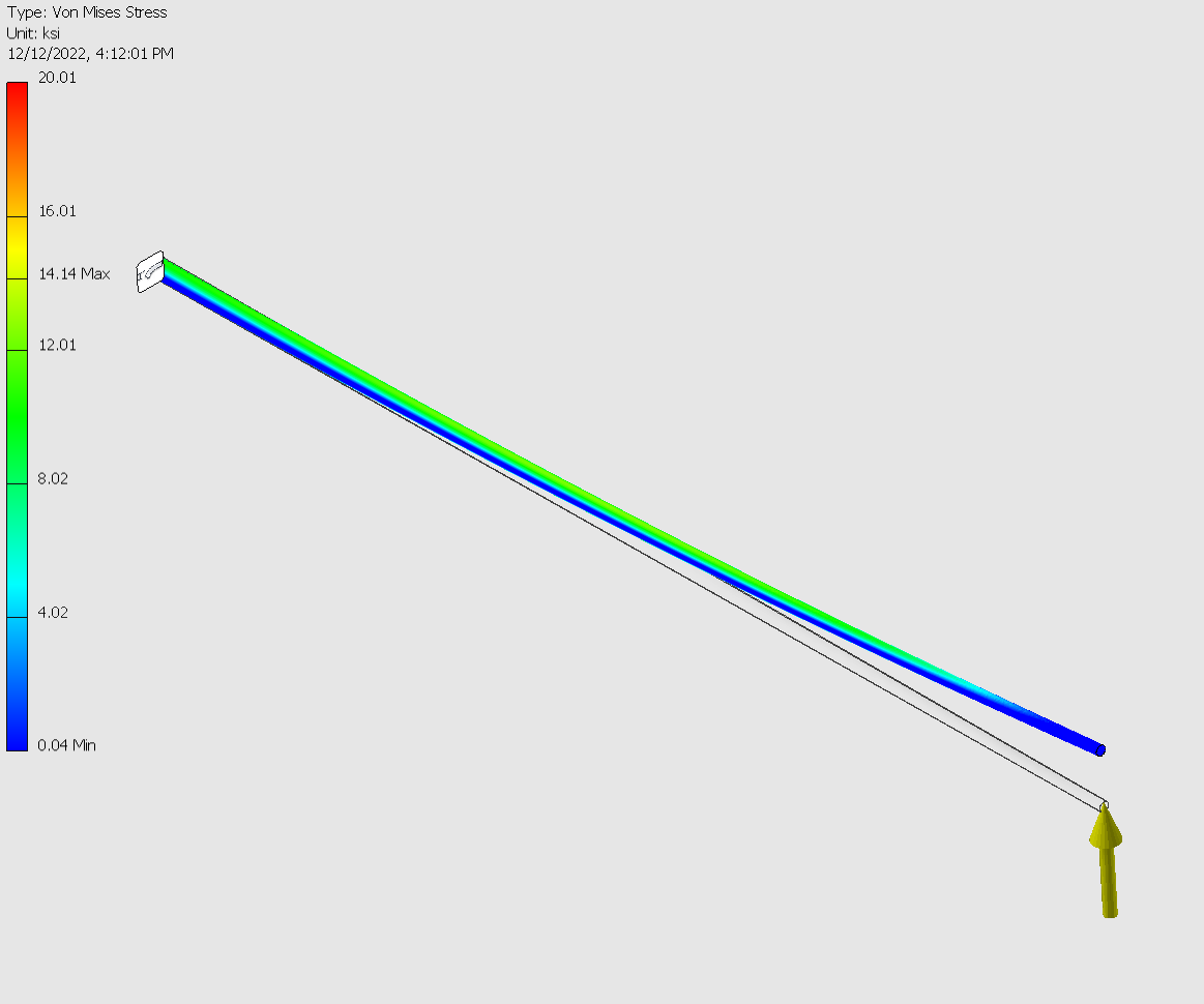
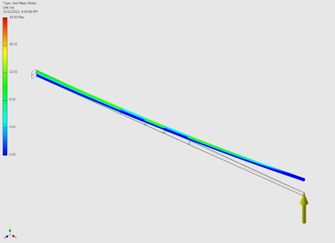
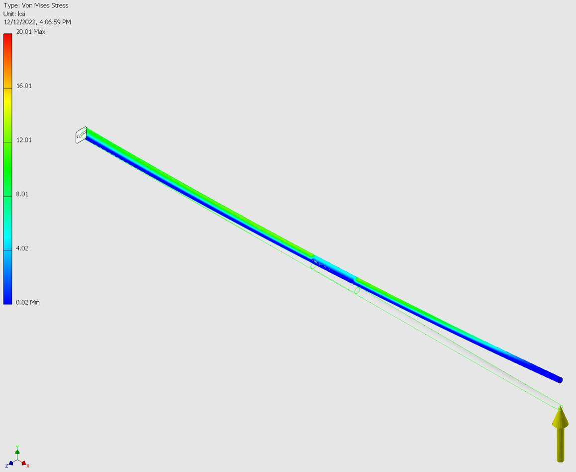
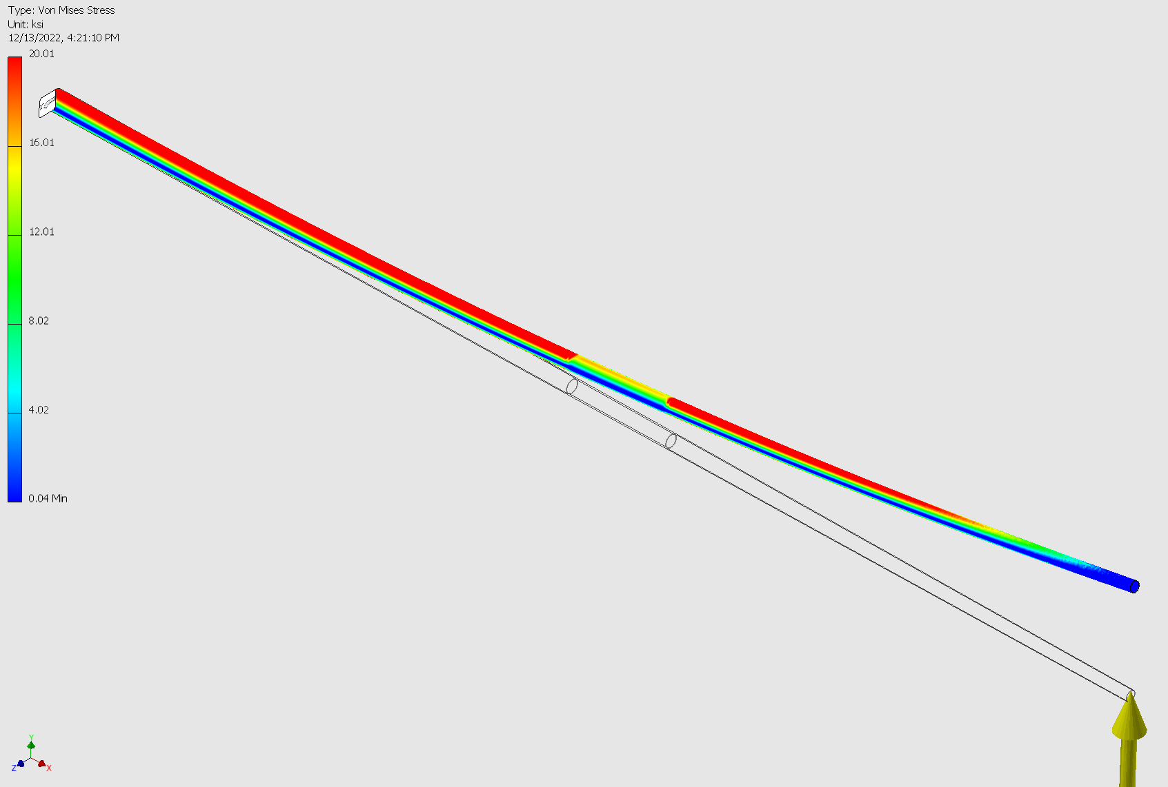
I modeled the fore-spar with the diameter and thickness varying according to actual measurements. I made 3 models one of an ideal mast without sleeves. One with the sleeve from original build and a third with the original sleeve and the repair sleeve.
I used stock carbon fiber strength data as inputs. It’s likely modern layups have different properties than 40 years ago.
I loaded each model identically. The model is a simple cantilevered beam. I used a point load of 1000 lbs at the tip of the mast. Actual loading is asymmetrically distributed along the length. A rule of thumb is 1.5-2 lbs/ft^2 for moderate to high winds. The point load modeled at the tip is much more than would ever occur and more than a distributed load. I often use more extreme loading when comparing multiple models, if you keep the same loading and only change the geometry you get an idea of how the changes affect overall strength.
The windward side is in tension and the leeward side is in compression. Think of the load arrow as the direction of the wind.
None of the options, even with the extreme loading, show excessive stress. Keep in mind the the displayed deflection is exaggerated.
No sleeve
Factory sleeve
Factory sleeve and repair sleeve
I’ll get closer views of the FEA models tomorrow.
Aloha Adam,
No worries, just needed a little push.
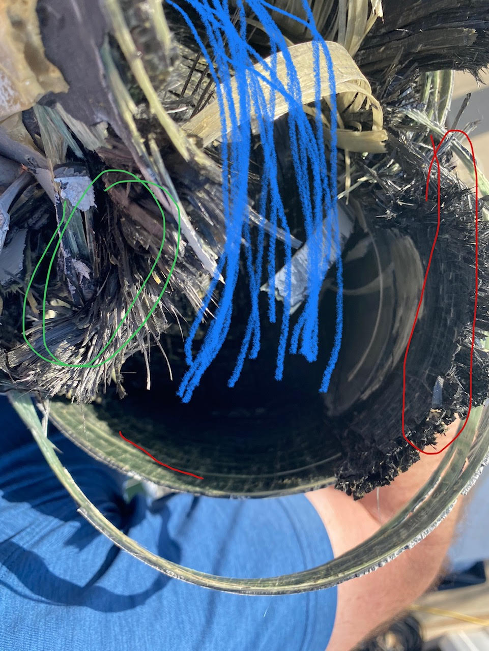
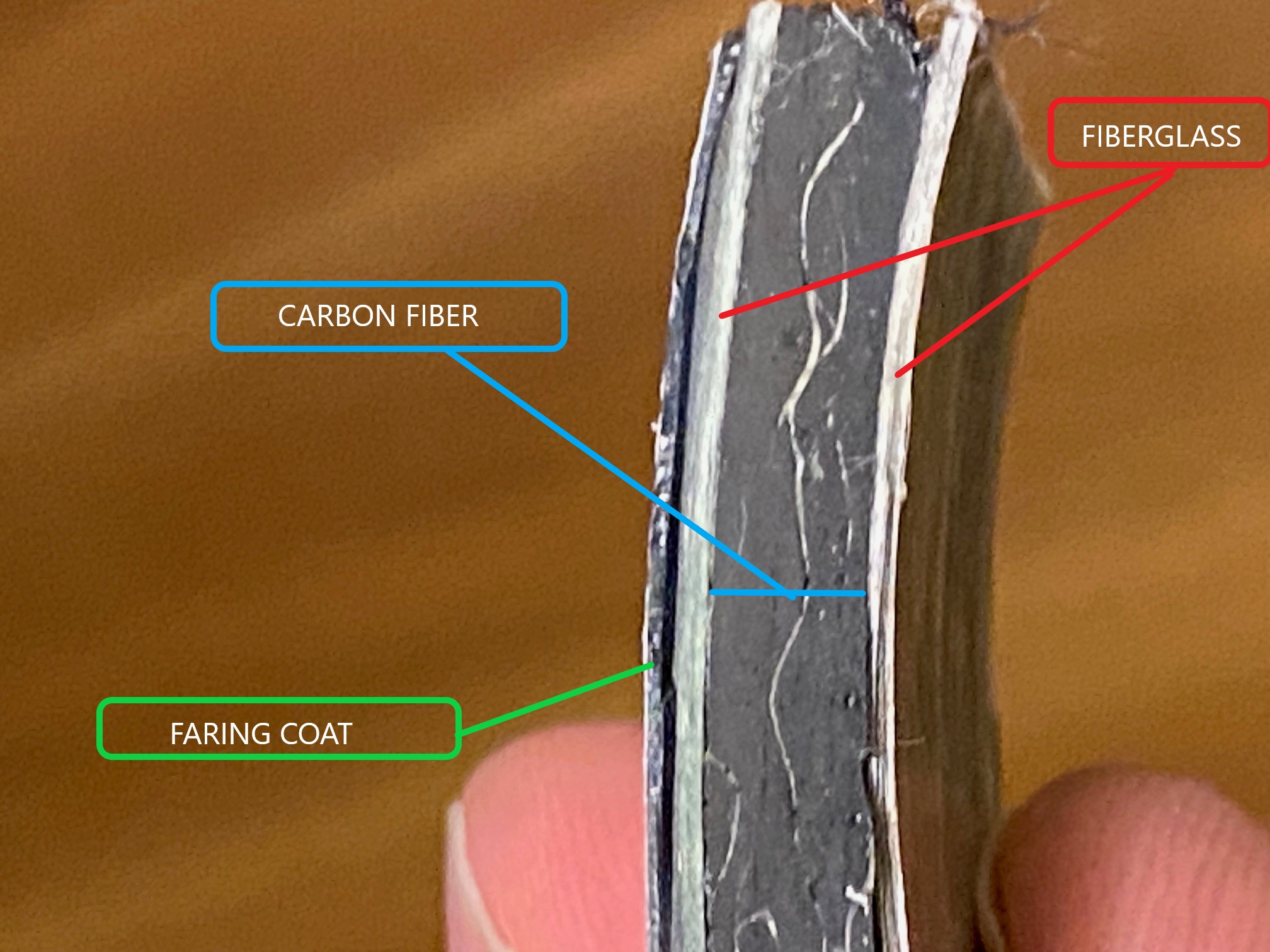
In the break zone on Vaimana’s mast the windward fibers pulled away from the fiberglass circumferential winding (blue in photo). The leeward fibers folded over. The forward 1/4-1/3 of the mast looks like it has a lot of fiber pull out associated with a tension break (red). The area right behind the mast track also had similar pull out (green).
BTW anyone know where I can get some of this aluminum sail track?
Correction, the above analysis were done with a 500 lb load at the tip not 1000 lbs.
Below is the mast with the factory sleeve and 1000 lb load at the tip. Don’t worry about the red its still about 1/3 of the ultimate strength.
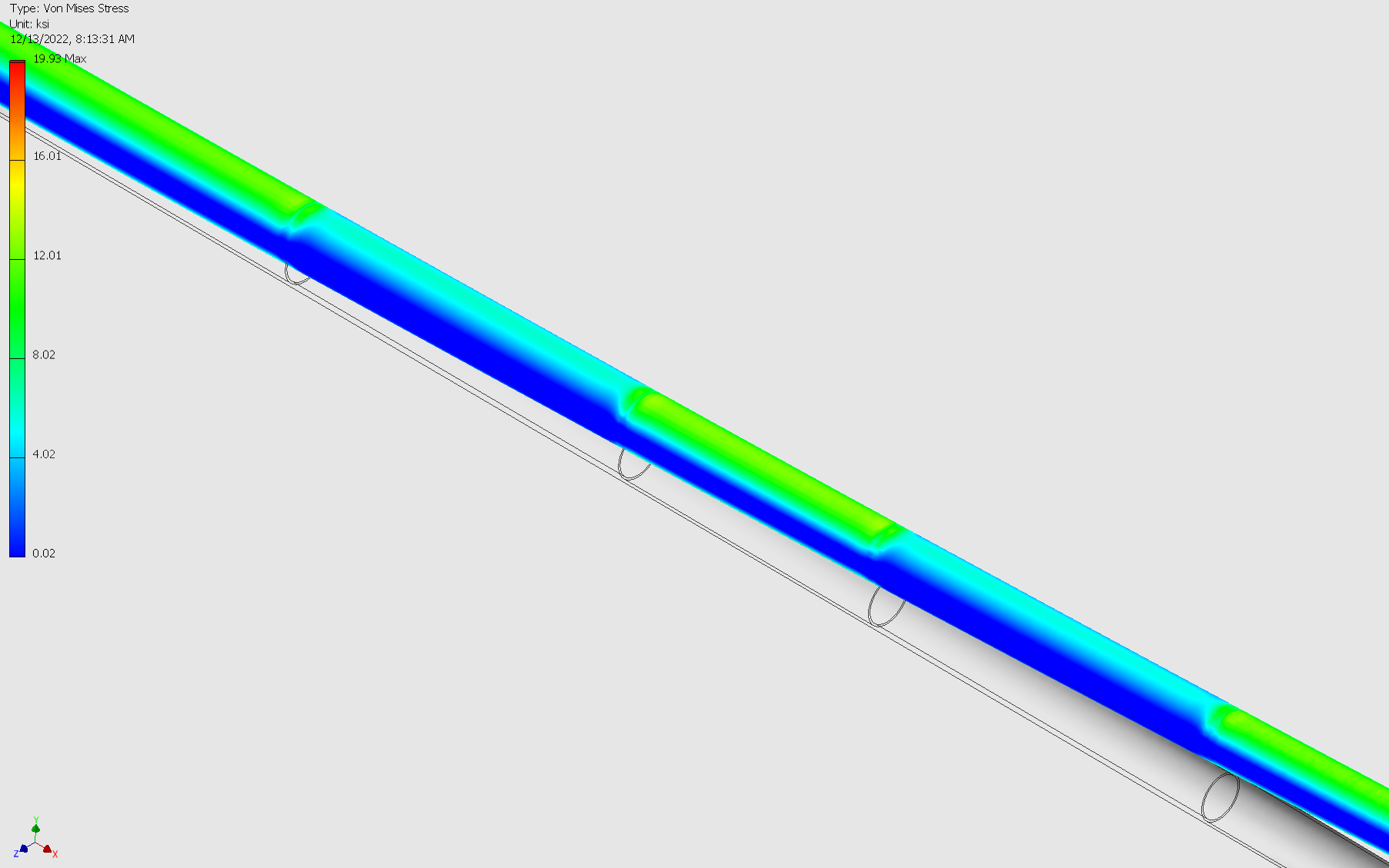
These next two are just closer views of the above near the sleeves 500 lb load at tip. No extreme stress areas.
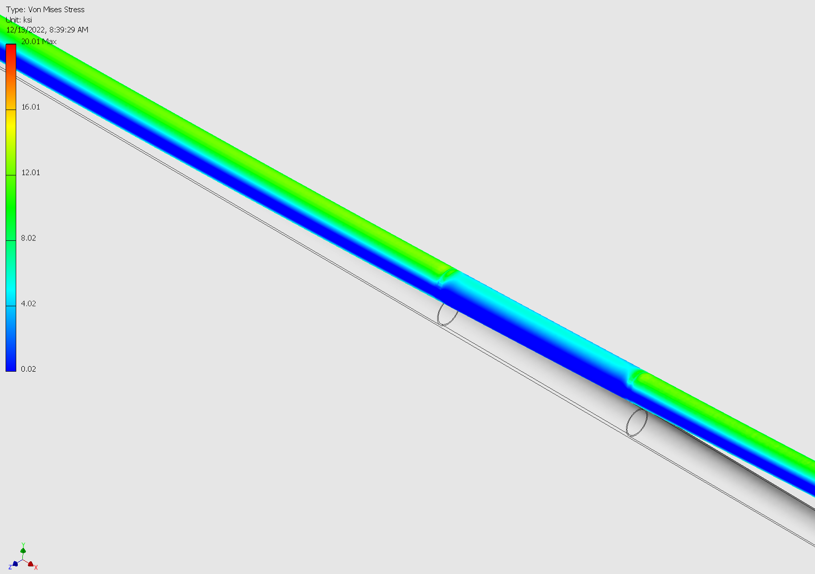
What I see is the fracture zone looks like the load pattern from the model. The two high loaded sides windward (tension) and leeward (compression) collapsed and the remaining smaller forward and aft areas tore. Still not sure what the cause was.
Everything wears out eventually even us…
Hi Adam,
Scary story. Glad no one got hurt. I was curious if you were using any running rigging stays when this happened.
Thanks
Karl
ALOHA Karl, " running rigging." pertains to all the of the lines to control the sails halyards, sheets, ect. freedom boats have self standing masts that dont require any “standing rigging” A
Adam, Oh, maybe I’m calling it by the wrong name. I have a 1979 FF40AC, new to me. Thats what the seller called them. So what I’m talking about is 2 cables that run from the top of the mast down to about 6ft above the deck and are attached to a fiddle block for tensioning. These attach to the toe rail wherever is good, and you can easily move them around. I heard some people don’t use them at all and that it’s a matter of preference. I hope that makes sense. Do you still have the same boat and how’s everything going?
Thanks
Karl
Running backstays, I think maybe you mean…?
Moy, Yeah. That makes sense
Here is a status update for the mast repair:
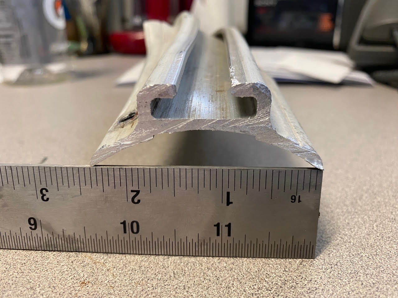
I cut some samples of the mast and took pictures of the cross sections along and perpendicular to the unidirectional fibers. The wall thickness is about 0.291” thick the carbon fiber portion is 0.215” thick. It appears to be an all unidirectional layup. It doesn’t look like it is a filament winding type layup. There is a thin layer of fiberglass wound around the circumference on either side of the CF. A fairing coat of filler is applied on the outside. The fiberglass layers were easily removed with my fingernails.
5X end grain
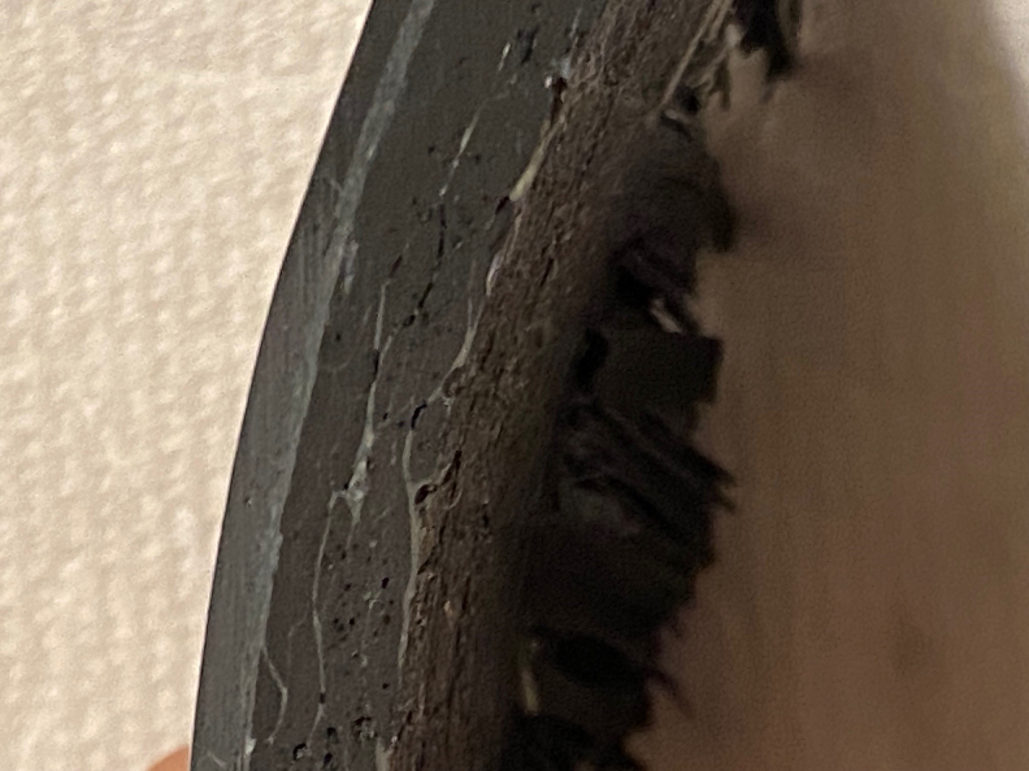
5X end grain (There are some voids in the layup seen from the end grain this is about 2” from the break)
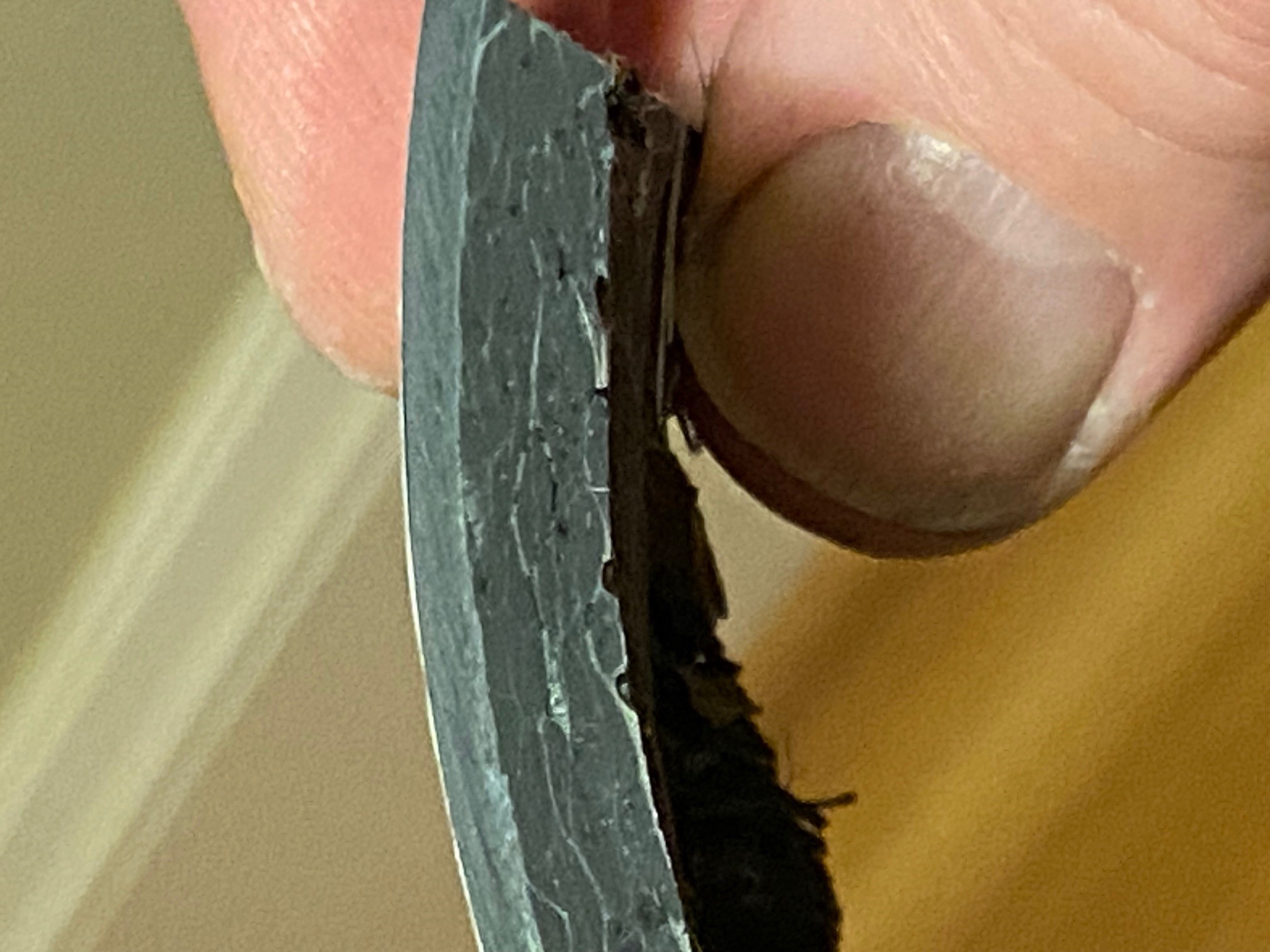
5X end grain